
Ill collect any wiring diagrams for the R125 i find here
Download all these R125 wiring diagrams from here
R125 technical manual https://sites.google.com/view/yamahayzf-r125ultimatebible/r125-technical-data
⚠️ Safety First: Never probe wires by stripping the insulation with a knife. This leads to "green rot" (corrosion) inside the wires. Always use proper back-probing pins or non-destructive testing methods.
1. The Three Main Harness Sections
To make the diagram less intimidating for your readers, break it down into these three functional "maps":
The Power & Charging Map: Battery - Main Fuse Regulator Rectifier Stator.
The Ignition & Starting Map: ECU Ignition Coil Starter Relay Safety Switches (Stand/Neutral).
The Lighting & Signaling Map: Headlight Relay $\rightarrow$ Handlebar Switches Indicators Tail Light.
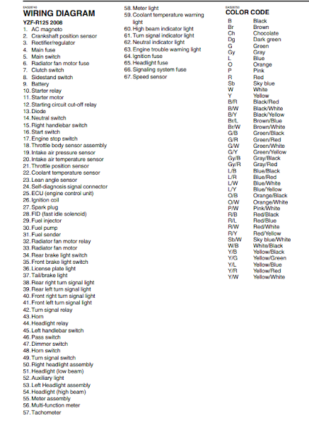
2. Color Code Quick-Reference
Standard Yamaha wiring colors for the R125:
Red (R): Constant 12V Battery Power.
Brown (Br): Switched 12V Power (Live when the key is ON).
Black (B): Ground / Negative.
Blue (L): Instrument Cluster / Interior Lighting.


R125 Ignition system wiring diagram ( Spark )

R125 fuel injection system wiring diagram

R125 Fuel pump wiring diagram

R125 starting circuit wiring diagram

R125 charging system

R125 lighting system circuit


Electrical Contact Cleaner: R125 connectors are prone to oxidation. Before assuming a component is dead, spray this into the plugs to ensure a clean metal-to-metal connection.
To help you pinpoint the exact break in your Yamaha YZF-R125 ignition or starting circuit, here is the "Common Fail Points" guide. On this bike, the loom is under constant stress near the front of the frame, which often leads to hidden wire breaks.
The "Headstock Snap" Zones
The most common electrical failures on the R125 occur where the wiring harness is zip-tied to the frame near the headstock. Constant steering movement causes the copper inside the wires to fatigue and snap, even if the plastic insulation looks perfect.
The Right-Hand Clip-On Bundle: Follow the wires from the Kill Switch and Starter Button. If the bike only cranks when the bars are turned to one side, you have a break in the Red/White or Blue/White wires in this section.
The Main Loom Bridge: Check the thick bundle of wires that crosses from the frame to the front fairing stay. This is where the Headlight Relay and Ignition Switch wires often fail.
R125 technical manual https://sites.google.com/view/yamahayzf-r125ultimatebible/r125-technical-data
No comments:
Post a Comment